
How to Calculate Pipe Gradient for Private Drainage
Table of Contents
- Why Pipe Gradient Matters in Private Drainage Design
- The Drainage Pipe Fall Formula Explained
- Converting Gradient to Drain Pipe Slope Percentage
- Using a Drainage Pipe Gradient Chart for Common Pipe Sizes
- How to Check Drain Pipe Gradient on Site
- Recommended Pipe Gradients and Minimum Slope Requirements
- Troubleshooting Incorrect Pipe Gradients
- Frequently Asked Questions
Last Updated: October 6, 2026
Why Pipe Gradient Matters in Private Drainage Design
Getting the pipe gradient right is the difference between a drain that clears itself and one you have to rod every few months. Pipe gradient is the fall, or drop in level, along a pipe run, expressed against the horizontal distance it covers. Get it wrong and wastewater slows down, solids settle, and blockages follow.
This guide shows you how to work out the fall, convert it to a percentage or ratio, and check it on site before you backfill.
Below, we cover the drainage pipe fall formula, worked examples, a gradient chart for common pipe sizes, and the minimum slope rules for private drainage, including the site-measurement part most guides skip.
The Drainage Pipe Fall Formula Explained
The drainage pipe fall formula is simple: fall equals gradient multiplied by the horizontal distance of the pipe run. Usually, you know the gradient you need and the distance you have, so you solve for the fall.
The formula works in three directions:
- Fall = gradient x distance (how much drop you need)
- Gradient = fall / distance (what slope you actually built)
- Distance = fall / gradient (how far the pipe can run)
Fall divided by distance gives you the gradient as a decimal. Multiply by 100 for a percentage, or convert to a ratio like 1 in 40.
Calculating Gradient from Pipe Measurements
Measure the total fall, then divide it by the horizontal distance. That is the gradient. A pipe dropping 50 mm over 2 metres gives 50 / 2000 = 0.025, or 2.5%, or 1 in 40.
Three things to remember:
- Measure horizontally, not along the pipe itself
- Keep units consistent (both in millimetres or both in metres)
- Measure from the invert, the inside bottom of the pipe, not the top
Always measure the horizontal distance between the two invert points, not the angled length of pipe. On a long run, the difference can push your calculated gradient off enough to fail a site check.
Converting Gradient to Drain Pipe Slope Percentage
To turn a gradient into a drain pipe slope percentage, multiply the decimal by 100. A gradient of 0.025 becomes 2.5%. Ratios work in reverse: a 1 in 40 slope means 1 unit of fall per 40 units of run, so 1 / 40 = 0.025, or 2.5%.
Here is the quick conversion:
| Gradient | Percentage | Ratio | Fall per metre |
|---|---|---|---|
| 0.01 | 1% | 1 in 100 | 10 mm |
| 0.0125 | 1.25% | 1 in 80 | 12.5 mm |
| 0.025 | 2.5% | 1 in 40 | 25 mm |
| 0.033 | 3.3% | 1 in 30 | 33 mm |
| 0.05 | 5% | 1 in 20 | 50 mm |
Most private drainage sits between 1 in 80 and 1 in 40. Steeper than that and liquids outrun solids. Flatter than that and the pipe cannot clean itself.
Working Through a Real Drainage Calculation
A 12 metre run to a new inspection chamber needs a 1 in 60 gradient. Divide 1 by 60 to get 0.0167, then multiply by 12 metres, giving 0.2 metres, or 200 mm of fall.
A 6 metre branch at 1 in 40 needs 1 / 40 = 0.025, times 6 = 0.15 metres, or 150 mm of fall.
The gradient formula never changes with pipe size. What changes is the minimum gradient you are allowed to use, which depends on the diameter of the pipe and the number of properties it serves.
Using a Drainage Pipe Gradient Chart for Common Pipe Sizes
A drainage pipe gradient chart saves you redoing the maths every time. Match your pipe diameter and the number of dwellings it serves, then read off the minimum gradient. Smaller pipes need steeper gradients because they carry less flow. Larger pipes can run flatter and still stay self-cleansing.
The key term is self-cleansing velocity: the flow speed needed to keep solids moving rather than settling. A flatter pipe drops below that speed and silts up.
Below is a practical reference chart for private drainage, based on common guidance for foul and surface water systems serving a single dwelling, assuming a uniform gradient with no backfall.
| Pipe diameter | Typical minimum gradient | Fall per metre | Notes |
|---|---|---|---|
| 110 mm | 1 in 80 | 12.5 mm | Common for single-dwelling foul runs |
| 110 mm | 1 in 40 | 25 mm | Preferred where site levels allow |
| 150 mm | 1 in 100 | 10 mm | Used for longer runs or multiple dwellings |
| 150 mm | 1 in 60 | 16.7 mm | Balances fall and self-cleansing |
| 225 mm | 1 in 150 | 6.7 mm | Typically for shared or commercial systems |
Where the run is long or the fall available is tight, stepping up to a larger diameter lets the pipe run at a gentler slope and still meet the minimum.
Always check the specific requirements for your project. Approved Document H gives minimum falls for foul and surface water drainage in England and Wales, and the sewerage undertaker may impose stricter standards where you connect to a public sewer.
How to Check Drain Pipe Gradient on Site
Checking drain pipe gradient on site comes down to two measurements: the fall between two points, and the horizontal distance between them. Get both, then run the formula. This section gives you the full site workflow, including how to set invert levels and what to do when the numbers do not work.
Step-by-step measurement workflow
- Establish a datum. Set a temporary benchmark at the upstream invert, the inside bottom of the pipe where it leaves the first chamber. Mark it on a timber peg or the chamber wall with a permanent marker.
- Set up your level. A laser level is fastest for long runs. A spirit level and straight edge works for short branches. A string line pulled tight between two pegs is the traditional method and still reliable if you account for sag.
- Measure the fall. Take a reading at the upstream invert and one at the downstream invert. The difference is your fall. With a laser, keep the beam parallel to the pipe route, not tilted.
- Measure the horizontal distance. Use a tape measure along the ground directly above the pipe centreline, not along the pipe itself. On a 1 in 40 slope the difference is small over a few metres, but on a 30 metre run it can push your calculated gradient outside the permitted range.
- Calculate the gradient. Divide fall by horizontal distance. For example, 250 mm fall over 10 metres gives 250 / 10000 = 0.025, or 1 in 40.
- Compare against the minimum. Check your result against the chart for your pipe diameter and the applicable standard. If it is too flat, you need more fall, a larger pipe, or a redesign.
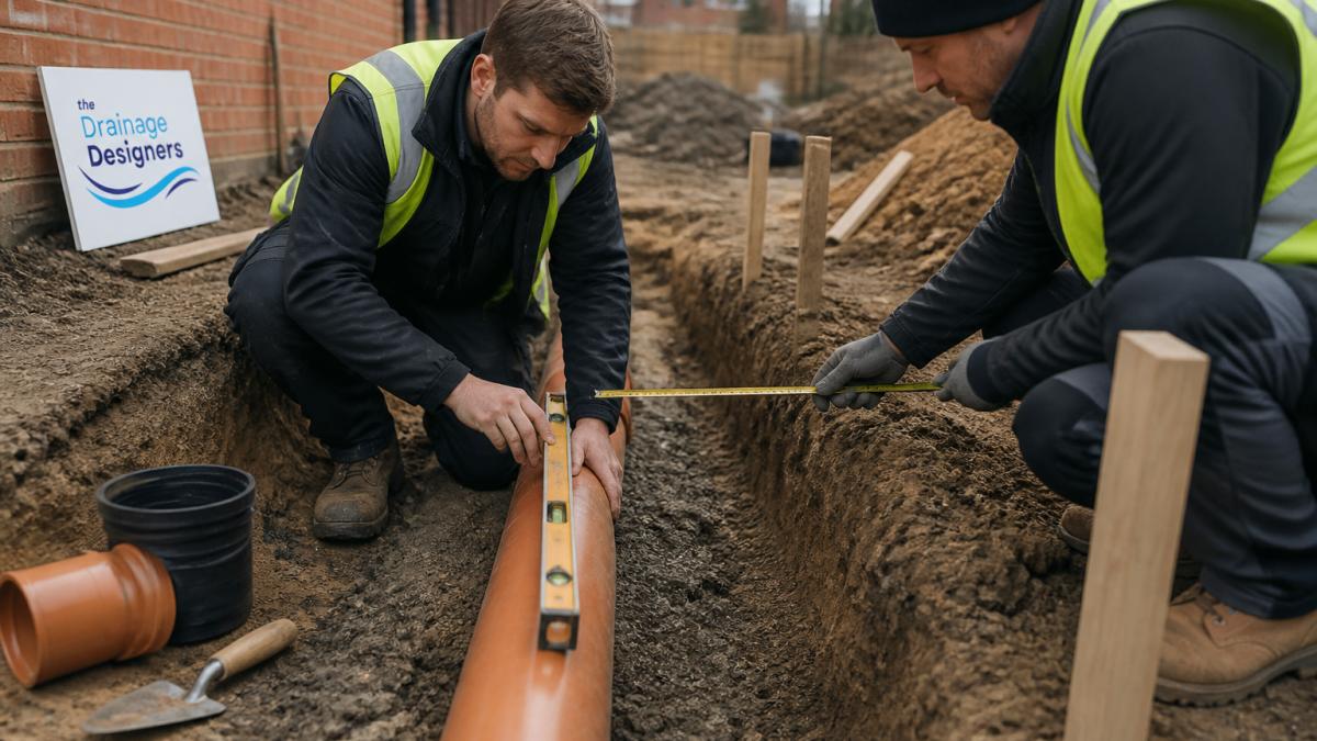
Setting invert levels and connection elevations
The invert level is the inside bottom of the pipe at a given point. When you connect to an existing chamber or sewer, the outgoing invert sets the maximum height for the incoming pipe. Work backwards from the receiving chamber: measure the outgoing invert, subtract the required fall for your run, and that gives the target invert at the upstream end.
For example, if the outgoing invert is 800 mm below ground and your run is 15 metres at 1 in 60, the fall is 250 mm, so the upstream invert must be at least 1050 mm below ground. Check this leaves enough cover, typically 600 mm in a garden or 900 mm under a driveway, though local requirements may vary.
Common mistakes and how to avoid them
- Measuring along the pipe instead of horizontally. Always measure the horizontal distance between invert points.
- Forgetting pipe wall thickness. Invert levels refer to the inside bottom, not the outside. A 110 mm pipe has a wall thickness that affects where the invert sits relative to the trench bottom.
- Checking after backfilling. Once the trench is filled, correcting a bad slope means digging it all out again. Check and record the gradient before you cover anything.
- Ignoring ground movement. On soft ground the pipe can settle after backfilling and create a belly. Bed it on a firm, uniform layer of granular material and compact properly.
Do not lay pipe to a gradient and then check it after backfilling. Once the trench is filled, correcting a bad slope means digging it all out again. Check and record the gradient before you cover anything.
If the available fall is less than the minimum for your pipe size, you may need to increase the diameter, add a pumped solution, or redesign the layout. Catching this at design stage is far cheaper than fixing it on site.
Recommended Pipe Gradients and Minimum Slope Requirements
Recommended gradients for private drainage sit between 1 in 40 and 1 in 110, depending on pipe size and the load it carries. Flatter than 1 in 110 and the pipe will not reliably self-cleanse.
For private drainage in England and Wales, the design rules sit in Approved Document H of the Building Regulations, which sets out the fall requirements for foul and surface water drainage. You can read the current guidance via Approved Document H, drainage and waste disposal. Local authority building control and the Lead Local Flood Authority will check your scheme against it.
The general principle: use the steepest gradient your site allows, up to about 1 in 40. Steeper risks separating liquids from solids; flatter risks silting.
Where surface water connects to a public sewer, the sewerage undertaker’s own standards apply on top of the building regulations. Check those before finalising the design.
Troubleshooting Incorrect Pipe Gradients
Most gradient problems fall into three types: too flat, too steep, or inconsistent along the run. Each has a different fix.
- Too flat: the pipe silts up. Fix by increasing the diameter, shortening the run with an extra chamber, or finding more fall upstream.
- Too steep: liquids outrun solids and the pipe blocks further down. Fix by breaking the run with a backdrop or rest bend.
- Inconsistent: the pipe dips or rises mid-run. Fix by re-laying to a uniform gradient with proper bedding support.
A common mistake is assuming a gradient that works for one pipe size works for all. A 110 mm pipe and a 150 mm pipe have different minimum falls for the same flow.
If your plans have come back with drainage conditions, the issue is often a gradient that cannot be achieved on site. That is usually solvable, but it needs catching at design stage, not on the day the digger arrives.
Getting the gradient wrong is one of the most common reasons drainage schemes come back with conditions attached. At The Drainage Designers (Woodvale consulting Ltd), we handle the full process, from site visits and flood risk assessments through to securing local council approvals, so the numbers work before anything is built. Our nationwide service covers domestic extensions and commercial developments alike, with a transparent customer charter and a focus on getting the design right first time. Get in touch to talk through your project. https://thedrainagedesigners.co.uk
Frequently Asked Questions
How do you calculate the gradient of a drainage pipe?
Divide the fall by the horizontal distance of the pipe run. For example, a 100mm fall over 4 metres gives 100 ÷ 4000 = 0.025, which is a 1 in 40 gradient or 2.5%. Always measure the horizontal distance, not the length along the pipe itself, because the pipe runs at an angle.
What is the minimum gradient for a private drainage pipe?
Building Regulations typically require a minimum fall of 1 in 80 for 110mm foul drainage pipes. Smaller pipes need steeper gradients to maintain self-cleansing velocity. A 1 in 40 gradient is commonly used for 110mm pipes as it provides a good balance between flow velocity and pipe capacity.
How do you convert a pipe gradient ratio into a percentage?
Divide 100 by the ratio number. A 1 in 40 gradient becomes 100 ÷ 40 = 2.5%. A 1 in 80 gradient becomes 100 ÷ 80 = 1.25%. This percentage represents the fall in millimetres per metre of horizontal pipe run.
What happens if a drainage pipe is laid too flat or too steep?
Too flat and waste solids settle instead of flowing, causing blockages. Too steep and liquids drain faster than solids, leaving debris behind. Both scenarios lead to repeated blockages and potential surcharge. The target is self-cleansing velocity, typically around 0.7 to 1.0 metres per second for foul drainage.