
Drainage System Design Standards for Architects
Table of Contents
- Understanding Drainage System Design Standards
- Building Regulations Part H: Core Requirements
- Sustainable Drainage Systems (SuDS) and Flood Risk
- Site Leveling, Fall Requirements, and Topography
- Drainage Design Software for Architects
- Drainage Strategy Report for Planning
- Climate Change Adaptation and Lifecycle Costs
- Conclusion
Understanding Drainage System Design Standards
Drainage system design standards for architects represent a critical intersection of regulatory compliance, engineering precision, and site-specific conditions. These standards ensure that water, both foul and surface, moves safely away from buildings and landscapes without causing flooding, environmental damage, or structural failure. At The Drainage Designers (Woodvale consulting Ltd), we work with architects and developers across the UK to translate these technical requirements into designs that satisfy planning authorities while serving the practical needs of the project.
The complexity lies not in the standards themselves, but in applying them correctly to each unique site. Fall requirements, hydraulic calculations, soil permeability, and regulatory frameworks all interact. Get one wrong, and your design comes back from the Local Authority with conditions or, worse, a rejection. This guide walks through the standards that matter most, how they connect to Building Regulations, and how modern design workflows integrate them.
Building Regulations Part H: Core Requirements
Building Regulations Part H sets the baseline for all drainage design in England. It covers foul drainage, surface water drainage, and the separation between them. The regulation exists to protect public health and prevent environmental damage, which is why it’s non-negotiable in any new build or major renovation.
Part H requires that foul drainage from toilets, sinks, and showers connects to either a public sewer (where available) or a private treatment system such as a septic tank or treatment plant. Surface water, rainfall runoff from roofs and hardstanding, must be managed separately. This separation is fundamental. Mixing the two overloads treatment systems and creates compliance issues.
Foul and Surface Water Separation
Foul and surface water separation is not optional; it’s a statutory requirement under Building Regulations Part H. Foul water contains human waste and must be treated before discharge. Surface water is relatively clean and can often be managed on-site through infiltration or attenuation.
The practical implication is straightforward: your drainage layout must use separate pipe runs from the building to the point of discharge. A common mistake is assuming that a single combined system can be split downstream, it cannot. The design must separate the flows at source.
For surface water, you have three discharge options in order of preference: infiltration (soakaway), watercourse (stream, ditch, pond), or public sewer. If infiltration is viable, meaning the soil has adequate permeability, it’s the preferred method. If not, a watercourse discharge requires consent from the Environment Agency or local water authority. Public sewer connection is the fallback when neither infiltration nor watercourse discharge is feasible.
Hydraulic Calculations and Pipe Sizing
Hydraulic calculations determine the pipe diameter and gradient required to move the design flow rate without surcharging or backing up. This is where many architects need support, as the calculations require understanding catchment area, rainfall intensity, and pipe capacity.
The design flow rate for foul drainage is based on the number of occupants and water-usage assumptions. For a four-bedroom house, Building Regulations assumes a certain daily flow, and the pipe must be sized to handle peak flows without pressure buildup. Undersizing the pipe creates blockage risk; oversizing wastes money and can cause sediment deposition.
Surface water flow rates depend on the catchment area (roof and hardstanding) and the rainfall intensity. The UK uses a standard design storm, typically a 1 in 40 year return period for most residential development, though this can change based on flood risk assessment. The pipe diameter is calculated using Manning’s equation or similar hydraulic methods to ensure the pipe can convey that flow at the specified gradient.
A minimum gradient of 1:40 is typical for foul drains (meaning 1 metre drop per 40 metres of pipe run), though this varies with pipe diameter and material. Surface water pipes often run at shallower gradients because the flow rates are higher and the pipes are larger. If your site topography doesn’t allow the required fall, you’ll need a pumped system, which adds cost and maintenance liability.
Sustainable Drainage Systems (SuDS) and Flood Risk
Sustainable Drainage Systems represent a shift away from traditional pipe-and-culvert approaches toward managing water where it falls. SuDS integrate surface water management with amenity and biodiversity benefits, reducing flood risk whilst improving site quality.
The concept is simple: slow the water down, let it infiltrate or evaporate, and only discharge to a watercourse or sewer what you cannot manage on-site. This reduces peak flow rates, alleviates pressure on public sewers, and reduces flooding downstream. Modern planning policy, particularly in areas designated as flood risk zones, increasingly mandates SuDS as part of the drainage strategy.
Return Periods and Attenuation Design
Return periods define the severity of rainfall event your drainage system must handle. A 1 in 40 year return period means a rainfall event of that intensity occurs, on average, once every 40 years. Most residential schemes use 1 in 40 year return periods for the main design storm. Higher-risk areas or critical infrastructure may require 1 in 100 year or even 1 in 200 year protection.
Attenuation is the temporary storage of surface water during a rainfall event, releasing it gradually so that the outflow rate doesn’t exceed the site’s discharge capacity. This is typically achieved through detention ponds, underground tanks, or permeable surfaces that retain water temporarily. The volume of attenuation required is calculated by comparing the inflow volume (rainfall over the catchment) to the allowable outflow rate, then sizing a storage reservoir to hold the difference.
For a 1 in 40 year return period, you might need to store 50-150 cubic metres of water temporarily, depending on site size and discharge rate. This storage can be above ground (visible pond) or below ground (tank or permeable pavement). The choice affects site layout, cost, and maintenance requirements.
Permeable Paving and Retention Solutions
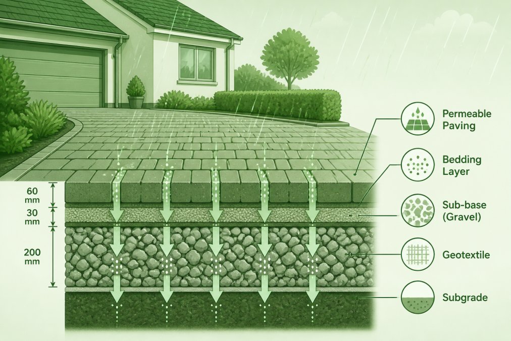
Permeable paving allows rainfall to infiltrate through the surface rather than running off into drains. It’s commonly used on driveways, car parks, and pathways. The paving sits on a permeable base layer (often gravel or recycled aggregate) with a geotextile membrane to prevent silt clogging. Water percolates through the pavement and base, infiltrating into the soil or draining to a perforated pipe that feeds a soakaway or attenuation tank.
Permeable paving reduces runoff volume, recharges groundwater, and provides amenity value. However, it requires adequate soil permeability and maintenance to prevent clogging. If the site has clay soils with poor infiltration, permeable paving alone won’t work, you’ll need a sub-base drainage system to pipe water away.
Retention ponds are larger surface features designed to hold water temporarily during heavy rainfall. They’re vegetated, often with native plants, and can serve dual purposes as amenity features and biodiversity habitats. Retention ponds require space and regular maintenance (mowing, sediment removal) but provide excellent visual impact and community benefit.
Site Leveling, Fall Requirements, and Topography
Your site’s topography dictates whether gravity drainage is feasible or whether you’ll need a pumped system. Fall is the vertical drop per unit of horizontal distance, expressed as a ratio (e.g., 1:40 means 1 metre drop per 40 metres).
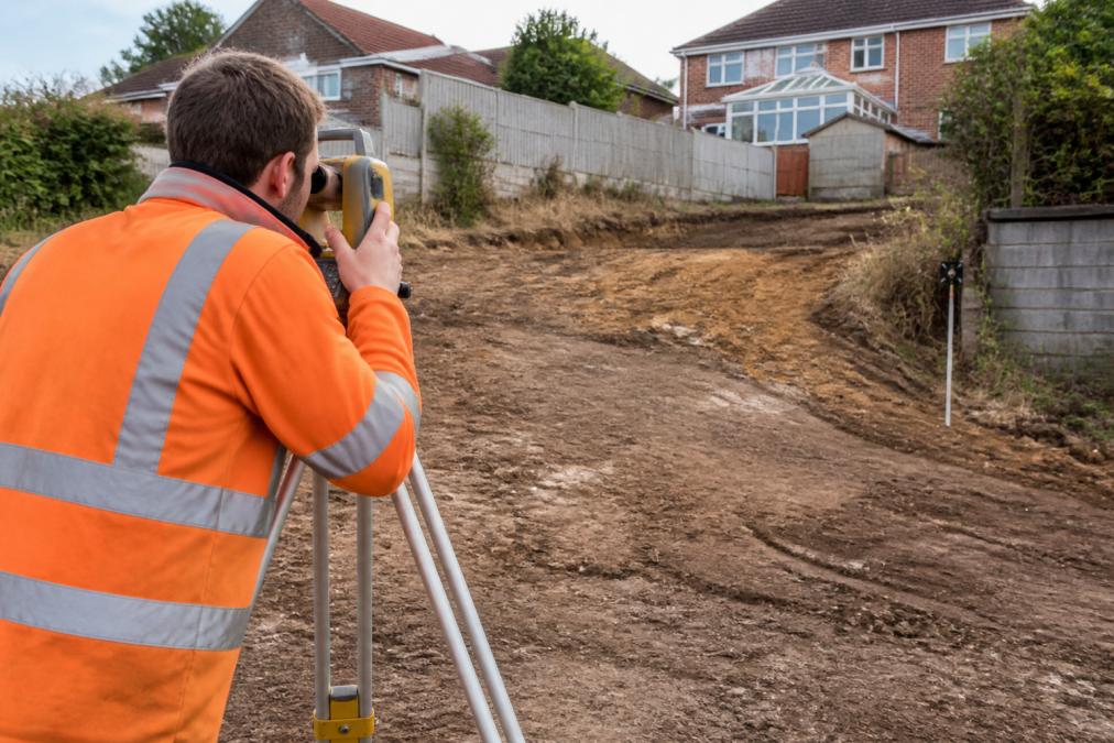
Before design work begins, the site must be surveyed to establish existing ground levels and proposed finished levels. This survey feeds into the drainage design, determining pipe routes, gradients, and discharge points. If your proposed finished floor level is higher than the available discharge point, gravity drainage isn’t possible, you’ll need to pump.
Pumping adds cost, requires electrical infrastructure, and introduces maintenance and failure risk. It’s avoided whenever possible. This is why early site surveying and level coordination between architect and drainage engineer is critical. A small change to finished floor level or site grading can eliminate the need for a pump entirely.
The topography also affects infiltration. Sloping sites with permeable soils are ideal for infiltration-based drainage. Flat sites with clay soils are problematic, water won’t drain away, and infiltration testing will likely fail. In these cases, attenuation and controlled discharge to a watercourse or sewer become necessary.
Drainage Design Software for Architects
Modern drainage design relies on specialist software to calculate hydraulic capacity, attenuation volumes, and infiltration rates. These tools automate the mathematics, reducing error and speeding up iteration.
Common software includes tools for pipe sizing, flood modelling, and SuDS design. Many of these packages integrate with CAD platforms, allowing you to model drainage layouts alongside architectural drawings. The output includes design reports, calculations, and drawings that satisfy planning and building control requirements.
The choice of software depends on project complexity and team expertise. Simple residential projects can be handled with spreadsheet-based tools. Complex multi-hectare developments with SuDS, attenuation ponds, and infiltration testing require dedicated modelling software. The Drainage Designers (Woodvale consulting Ltd) uses industry-standard tools to ensure designs are strong and defensible.
Drainage Strategy Report for Planning
A drainage strategy report is a formal document submitted with planning applications. It sets out how foul and surface water will be managed, demonstrates compliance with policy, and addresses flood risk. The report is your opportunity to convince the planning authority that your drainage approach is sound.
The report should include: existing site survey with levels, proposed finished levels, foul drainage route and discharge point, surface water management strategy (infiltration, attenuation, discharge), flood risk assessment findings, and compliance statements against Building Regulations Part H and local planning policy. If SuDS are proposed, the report explains how they integrate into the design and what maintenance arrangements are in place.
Lead Local Flood Authority Consultation
The Lead Local Flood Authority (LLFA) is the local council body responsible for flood risk management. For developments in flood risk areas or where surface water drainage is uncertain, early consultation with the LLFA is essential. They can advise on discharge rates, attenuation requirements, and any local flood risk constraints.
Consulting the LLFA early, ideally before detailed design, prevents costly redesigns later. Many LLFAs publish drainage and flood risk guidance specific to their area, including acceptable discharge rates and SuDS preferences. This guidance should inform your drainage strategy from the outset.
Planning Permission and Regulatory Compliance
Planning permission requires that your drainage design complies with Building Regulations and local flood risk policy. The planning officer will consult with building control and the LLFA to verify compliance. A well-prepared drainage strategy report, backed by calculations and site survey data, significantly increases the likelihood of first-time approval.
Common reasons for drainage-related planning rejections include: inadequate discharge rate calculations, failure to demonstrate infiltration testing, insufficient attenuation volume, or non-compliance with local SuDS policy. These are all preventable with proper design and documentation.
Climate Change Adaptation and Lifecycle Costs
Climate change is increasing rainfall intensity and frequency in the UK. Current design standards assume historical rainfall patterns, but future rainfall may exceed these assumptions. Forward-thinking drainage design incorporates resilience by oversizing attenuation, planning for increased runoff, and designing systems that can adapt.
This might mean designing attenuation for a 1 in 100 year storm instead of 1 in 40 year, or specifying permeable surfaces that can handle higher infiltration rates. The upfront cost is modest, but the long-term benefit, avoiding flooding during extreme events, is substantial.
Lifecycle costs matter too. A gravity-fed soakaway requires minimal maintenance. A pumped system requires electrical supply, regular servicing, and eventual replacement. A retention pond needs vegetation management and sediment removal. These ongoing costs should factor into your design decisions. The cheapest initial design isn’t always the cheapest over the building’s lifetime.
Drainage system design standards exist to protect your project, your occupants, and the environment. Compliance isn’t bureaucratic burden, it’s engineering rigour that prevents costly failures. The standards cover foul and surface water separation, hydraulic capacity, infiltration and attenuation, flood risk, and environmental protection.
Getting drainage right requires early engagement with site survey, topography, soil conditions, and regulatory requirements. This is where The Drainage Designers (Woodvale consulting Ltd) adds value. Our team combines technical expertise in hydraulic calculations, SuDS design, and regulatory compliance with practical experience navigating local authority requirements. We deliver drainage strategies that satisfy planning conditions, comply with Building Regulations, and protect your project on schedule. Get in touch to discuss your drainage requirements.
Frequently Asked Questions
What are the current Building Regulations for drainage systems?
Building Regulations Part H governs all drainage design in residential and commercial properties. Key requirements include proper separation of foul and surface water, hydraulic calculations to size pipes correctly, minimum 1:40 fall gradients, and compliance with the Building Safety Act. All drainage systems must be designed to prevent flooding, manage groundwater, and meet discharge rate standards set by your local water authority. Your drainage strategy report must demonstrate compliance before planning permission is granted.
How does drainage design software for architects improve compliance?
Specialised drainage design software automates hydraulic calculations, generates compliant drainage layouts, and produces the technical documentation required by building control and local authorities. These tools ensure pipe diameters, fall gradients, and attenuation volumes meet Building Regulations Part H and SuDS standards. They also help architects visualise the drainage system within site topography, reducing design errors and speeding up the planning approval process. Most modern platforms integrate with BIM workflows, improving coordination across disciplines.
What should a drainage strategy report for planning include?
A drainage strategy report for planning must cover site location and topography, foul and surface water drainage proposals, hydraulic calculations and pipe sizing, SuDS implementation details, flood risk assessment data, return period analysis (typically 1:100 year events), Lead Local Flood Authority consultation outcomes, and confirmation of compliance with Building Regulations Part H. The report should also address groundwater protection, discharge rates to existing sewers, and maintenance responsibilities. This document is essential for obtaining planning permission and building control sign-off.
How do architects ensure drainage designs comply with local authority requirements?
Architects must engage with the Lead Local Flood Authority early in the design process to understand local flood risk, surface water management strategies, and SuDS requirements specific to your area. Each local authority interprets Building Regulations Part H differently, so consultation is critical. Your drainage strategy report should reference local development plans, flood maps, and any area-specific guidance. Working with experienced drainage designers familiar with your local authority's expectations significantly improves first-time approval rates and prevents costly revisions.
This article was written using GrandRanker