How to Streamline Drainage Design Workflows
Table of Contents
- Why Drainage Design Workflows Need Streamlining
- Integrating BIM Outputs Into Your Drainage Design Process
- Automating Pipe Network Design and Hydraulic Modelling
- Drainage Design Software Tools That Reduce Manual Work
- SuDS Compliance Checklist for Faster Regulatory Approval
- Understanding the LLFA Approval Process
- Common Bottlenecks and How to Avoid Them
- Conclusion
Last Updated: August 21, 2026
Why Drainage Design Workflows Need simplifying
Every drainage project begins with translating site conditions, regulatory requirements, and engineering principles into compliant designs. Yet most teams approach this with fragmented processes, manual handoffs between software systems, and approval cycles that stretch weeks longer than necessary.
Traditional drainage design workflows create bottlenecks at every stage. Engineers spend hours re-entering data between BIM models and hydraulic simulation software. Site surveys get manually transcribed into design calculations. Approval submissions require multiple revisions because initial designs miss local authority requirements or SuDS compliance criteria.
Simplifying drainage design workflows isn’t about working faster. It’s about removing friction that turns a straightforward technical process into an administrative burden. When your team moves from site analysis to hydraulic modelling to regulatory approval without translating between incompatible systems, you reclaim weeks of project time.
The Drainage Designers (Woodvale consulting Ltd) has spent years helping architects, developers, and in-house engineering teams identify where their processes leak time and compliance risk. The most efficient teams integrate their existing tools, standardise data handoffs, and front-load compliance checks so revisions become rare rather than routine.
Below, we’ll walk through specific workflow improvements that make the biggest difference: integrating BIM outputs without data loss, where automation saves the most time, which compliance checks prevent rejections, and how to structure your process so every project moves faster than the last.
Integrating BIM Outputs Into Your Drainage Design Process
BIM models contain rich geometric and spatial data, yet most drainage design workflows treat them as visual references rather than data sources. The disconnect happens because BIM outputs and drainage design software speak different languages: coordinate systems, object hierarchies, and attribute structures rarely align without deliberate translation.
The first step is establishing a standardised export protocol from your BIM environment. Define exactly which objects carry drainage-relevant information: site surfaces, proposed ground levels, existing utility corridors, and building footprints. Most BIM software allows you to tag these elements with custom metadata during modelling, then export that information in structured formats (IFC, XML, or CSV).
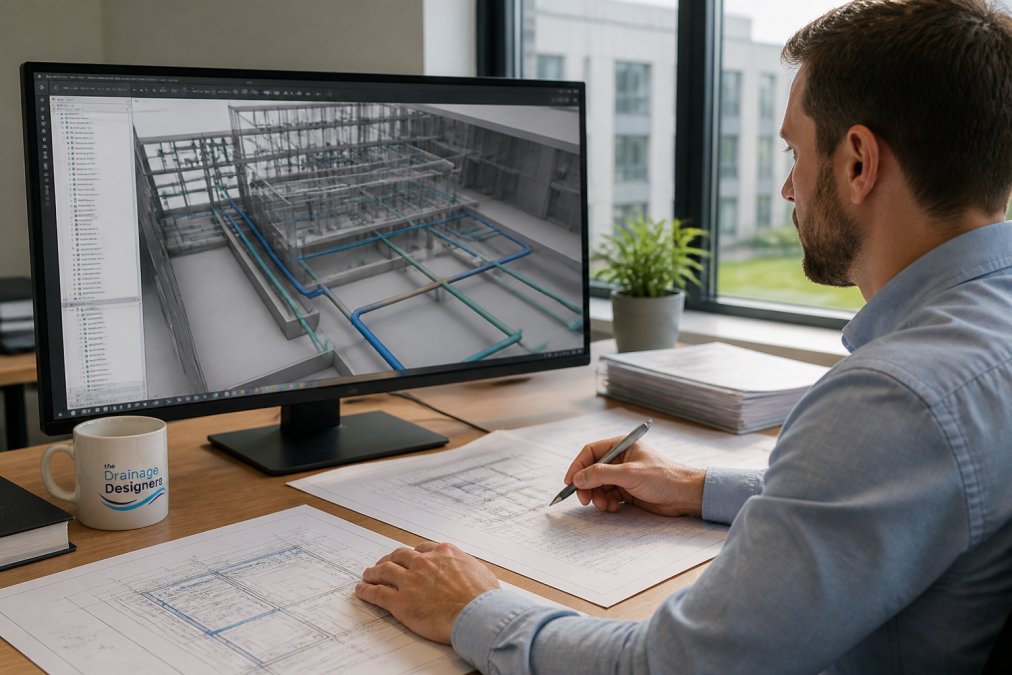
Once you have clean BIM data, map it into your hydraulic modelling environment without manual re-entry. Tools that support standard data exchange formats reduce transcription errors that propagate through your entire design. A single misplaced decimal in ground level data can invalidate downstream hydraulic calculations, often undetected until the Local Lead Flood Authority (LLFA) review (peer-reviewed research).
Export only the geometry and attributes that directly influence drainage design: site contours, building outlines, proposed surfaces, and existing drainage infrastructure. Too coarse and you lose critical information; too granular and you create noise that slows modelling.
Establish a single source of truth, typically the BIM model, and pull fresh drainage data at defined project milestones rather than working from static exports. The teams that move fastest establish this integration early, before detailed design begins. By the time hydraulic modelling starts, all necessary geometric data flows directly from the BIM environment.
Automating Pipe Network Design and Hydraulic Modelling
Pipe network design is inherently repetitive: define nodes, assign properties, calculate gradients, verify velocities, and iterate when results fall outside acceptable ranges. This is precisely where automation delivers the largest time savings.
Modern drainage design software can automate much of this cycle. Rather than manually sizing each pipe segment, define design parameters (minimum velocity, maximum velocity, minimum gradient, maximum cover depth) and let the system generate candidate pipe networks that satisfy all constraints. The software evaluates multiple routing options simultaneously, something that would take a human designer hours to work through manually.
The key to effective automation is parameterisation. Before automating, define your design rules explicitly. What velocity range is acceptable? What’s the maximum permissible cover depth? What gradients are feasible given existing infrastructure? These questions can only be answered by your design standards and local authority requirements.
Once parameterised, the software becomes a constraint solver. It explores the design space far more thoroughly than manual iteration, often identifying solutions that satisfy all criteria more elegantly than a designer working under time pressure would discover.
Hydraulic analysis verification follows naturally. Rather than running a single design through your hydraulic model, automation lets you test dozens of candidate networks in parallel. You can see which designs deliver the best performance against your objectives: lowest cost, smallest footprint, best resilience.
The transition from manual to automated design typically takes one project to get right. By the second project, you’re working at a pace that would have seemed impossible before automation.
Drainage Design Software Tools That Reduce Manual Work
Selecting the right software foundation determines whether your workflow becomes more efficient or simply shifts bottlenecks. The critical distinction isn’t between expensive and affordable tools, it’s between systems designed for design iteration and systems designed for documentation.
Design-focused tools prioritise rapid iteration. You change a parameter, the system recalculates immediately, and you see the impact on your design. Documentation-focused tools prioritise producing compliant outputs, which is important, but they often require multiple steps before you can evaluate a design change.
For most teams, the ideal approach combines both. A design tool handles the exploratory phase, testing pipe networks and evaluating hydraulic performance. A documentation tool then produces the formal drawings, calculations, and compliance statements required for regulatory submission. The two systems should exchange data cleanly so you’re not re-entering information.
Integration with your BIM environment matters more than raw feature count. If your chosen tool can’t read BIM data directly, you’re adding a manual translation step that defeats the purpose of automation. Similarly, if the tool outputs proprietary formats that don’t translate cleanly into your design documentation system, you’re creating another handoff point where errors creep in.
Many teams underestimate the value of template standardisation within their chosen tool. Rather than starting each project from scratch, build project templates that encode your standard design practices, typical pipe materials, standard node configurations, and default design parameters. New projects then inherit these standards automatically, reducing setup time and ensuring consistency across your portfolio.
The Drainage Designers (Woodvale consulting Ltd) works with teams across a range of software environments. The common thread among the most efficient practices is teams that have invested in mastering their chosen tool deeply, standardising their workflows within it, and integrating it cleanly with their BIM and documentation systems.
SuDS Compliance Checklist for Faster Regulatory Approval
Sustainable Drainage Systems (SuDS) compliance has become non-negotiable for most development projects. Yet many teams treat SuDS as a final checklist item rather than a design driver, leading to designs that technically satisfy SuDS principles but don’t integrate cleanly with the broader site layout. This typically triggers revision requests from planning authorities.
The efficiency gain comes from front-loading SuDS requirements into your design process rather than retrofitting them afterwards. Before designing your pipe network, identify which SuDS components your site can accommodate: permeable pavements, attenuation ponds, green roofs, bioswales. Map these spatially on your site model, allocate storage volumes, and verify that they satisfy runoff management requirements for your design storm.

A practical checklist ensures you’ve addressed key compliance points before submission:
- Runoff volume calculation for the 1 in 100 year storm (plus 40% climate change allowance) completed and documented (gov.uk)
- SuDS component storage volumes verified against calculated runoff requirements
- Infiltration rates determined through site testing or conservative assumptions from soil classification
- Maintenance access and inspection arrangements specified for all SuDS components
- Exceedance routing defined, where does water go if SuDS components reach capacity
- Adoption and maintenance responsibilities clearly assigned (developer, local authority, management company)
- Landscape integration confirmed so SuDS components function as amenity features
The teams that move fastest through regulatory approval integrate this checklist into their design workflow from the start. Rather than discovering a compliance gap during authority review, they’ve already verified each point and documented the evidence. When the LLFA or planning officer reviews the submission, they’re confirming compliance rather than identifying deficiencies.
Obtain published SuDS design guidance from your authority early, often before detailed design begins. This means you’re designing to the authority’s actual expectations rather than generic best practice.
Understanding the LLFA Approval Process
The Local Lead Flood Authority holds technical authority over drainage and flood risk for most development sites. Understanding their approval workflow, timescales, and common concerns dramatically improves your chances of first-time approval.
Most LLFAs publish formal consultation responses within 21 days of receiving a complete submission (gov.uk). However, "complete" has a specific meaning. Missing information, inadequate site surveys, incomplete hydraulic calculations, or unclear SuDS design automatically extends the timeline as the LLFA requests clarification. Each clarification cycle typically adds 2-3 weeks.
The most efficient approach is pre-submission engagement. Contact the LLFA early in your design phase with preliminary site information and a draft drainage strategy. Ask specifically: what information do you require for technical approval? What are your current concerns about this site? What SuDS components do you prefer? This conversation typically takes one hour and saves weeks of revision cycles later.
Different LLFAs have different priorities. Some emphasise infiltration-based SuDS; others prefer attenuation storage. Some have strict policies on exceedance routing; others are flexible provided residual risk is managed. Learning these preferences before detailed design means you’re designing to their actual requirements rather than discovering misalignment during formal consultation.
Documentation quality directly affects approval timescales. Clear, well-organised submissions with all required calculations, site surveys, and design justifications move through review quickly. Submissions that require the LLFA to hunt for information inevitably face delays.
The LLFA also coordinates with planning authorities. If the LLFA raises concerns about your drainage design, planning officers typically defer their decision pending LLFA sign-off. This means LLFA approval is often the critical path item that determines your overall project timeline.
Common Bottlenecks and How to Avoid Them
Most inefficiencies in drainage design workflows cluster around three recurring problems: data translation failures, compliance gaps discovered late, and approval cycles extended by incomplete submissions.
Data translation failures happen when information moves between systems without proper validation. A ground level value gets transposed, a pipe diameter gets misread, or a coordinate system doesn’t translate correctly. These errors often go undetected until hydraulic analysis reveals impossible results. The fix is implementing validation checks at every data handoff. Before importing BIM data into your hydraulic model, verify that critical parameters match your survey data.
Compliance gaps discovered during authority review represent sunk cost. You’ve invested design effort in a solution that doesn’t satisfy regulatory requirements. The prevention is straightforward: obtain the LLFA’s technical requirements before detailed design begins and verify your design against those requirements before submission.
Incomplete submissions are the single most common cause of extended approval timescales. Missing site surveys, inadequate hydraulic calculations, or unclear design justifications force the LLFA to request clarification. Each request cycle adds 2-3 weeks. Establish a submission checklist and verify completeness before sending anything to the authority.
Another frequent bottleneck is poor coordination between your design team and approving authorities. If your architect designs the site layout whilst your drainage engineer designs the drainage strategy independently, conflicts emerge late. The solution is integrating drainage design into the overall site design process from the beginning.
Teams that simplify their workflows address these bottlenecks systematically. They validate data at every handoff, engage authorities early, verify compliance before submission, and coordinate drainage design with overall site planning. These practices don’t require expensive tools or additional staff; they require process discipline and clear ownership of each workflow stage.
Simplifying your drainage design workflows isn’t about abandoning rigour or cutting corners. It’s about eliminating friction that turns a technically straightforward process into an administrative ordeal. The teams that move fastest through regulatory approval have built processes that catch errors early, satisfy authority requirements the first time, and integrate drainage design seamlessly with the broader project delivery.
The Drainage Designers (Woodvale consulting Ltd) helps teams implement exactly these improvements. Whether you’re managing a residential extension requiring LLFA consultation or a commercial development requiring full SuDS integration, our team brings proven workflows that accelerate approval and reduce revision cycles. Get in touch to discuss how we can simplify your next project’s drainage design process.
Frequently Asked Questions
What are the main bottlenecks in drainage design workflows?
Common bottlenecks include manual data entry between design tools, inconsistent BIM object definitions across projects, delays in Lead Local Flood Authority (LLFA) feedback cycles, and rework caused by incomplete site survey data. Automating pipe network design, standardising drainage templates, and establishing clear communication channels with local authorities can reduce these friction points significantly and accelerate your project timeline.
How do I ensure my drainage design meets SuDS compliance requirements?
Use a SuDS compliance checklist covering infiltration rates, surface water storage, maintenance access, and catchment modelling. Verify your design against your local authority's SuDS design guidance early, not after completion. Include watershed analysis and sustainable drainage systems assessment in your initial hydraulic modelling. Engage with your LLFA before finalising designs to confirm your approach aligns with their expectations and technical standards.
What role does BIM integration play in streamlining drainage workflows?
BIM integration eliminates duplicate data entry by linking drainage objects directly to your architectural and structural models. This improves interoperability between civil engineering workflows and design delivery phases, reduces errors during model handover, and enables automated reporting on design validation. Proper data exchange standards ensure your pipe network and hydraulic analysis remain accurate as the project evolves through design iterations.
How can we speed up LLFA approval without compromising compliance?
Submit designs that fully address LLFA requirements upfront by reviewing their technical guidance and flood risk assessment criteria before you start. Include geospatial data, stormwater runoff calculations, and storage node details in your initial submission. Establish a pre-submission meeting with your local authority to clarify expectations. This approach reduces back-and-forth revisions and accelerates regulatory approval, allowing your project to progress on schedule.
This article was written using GrandRanker