
Calculate Surface Water Runoff for Small Sites
Table of Contents
- What Is Surface Water Runoff and Why It Matters for Small Sites
- Understanding the Rational Method for Runoff Calculation
- Estimating Greenfield Runoff Rate for Your Site
- Step-by-Step: Calculating Surface Water Runoff in Practice
- Calculating Surface Water Storage Volume for Attenuation
- SuDS Drainage Strategy Requirements and Regulatory Compliance
- Common Mistakes to Avoid When Calculating Runoff
- When to Seek Professional Assessment
- Frequently Asked Questions
Last Updated: September 1, 2026
What Is Surface Water Runoff and Why It Matters for Small Sites
Surface water runoff is the flow of water across land surfaces following rainfall, moving downhill towards drainage systems, watercourses, or storage facilities. For small sites, residential extensions, new builds, or modest commercial developments, understanding runoff is essential because it directly affects planning approval, flood risk assessment, and compliance with local drainage requirements.
Councils and Lead Local Flood Authorities have tightened scrutiny of drainage proposals. They require evidence that your site won’t increase flood risk to neighbouring properties or overwhelm existing infrastructure. Without a credible surface water runoff calculation, your planning application faces rejection or conditions that delay your project.
This guide walks you through measuring catchment area, sourcing rainfall intensity data, applying the runoff coefficient, and calculating peak flow rate. A worked example shows the method step by step, plus guidance on when professional assessment becomes necessary.
Understanding the Rational Method for Runoff Calculation
The Rational Method is the standard approach for estimating peak flow rate from small catchments in the UK. It’s the method councils expect and the foundation of most surface water runoff calculations in planning submissions.
The formula is:
Q = C × I × A
Where:
- Q = peak flow rate (litres per second)
- C = runoff coefficient (dimensionless)
- I = rainfall intensity (millimetres per hour)
- A = catchment area (hectares)
The Rational Method assumes rainfall falls uniformly across your site and that runoff reaches its peak when the entire catchment area contributes to flow. This holds true for small sites (typically under 10 hectares), which is why it’s standard for residential and small commercial developments. You don’t need complex hydrological models, though professional tools improve accuracy.
One important limitation: the Rational Method doesn’t account for storage or attenuation. If your site includes a detention basin, swale, or permeable surface that temporarily holds water, the method calculates runoff before that storage takes effect.
The Key Variables: Rainfall Intensity, Catchment Area, and Runoff Coefficient
Each variable directly controls your final runoff figure.
Rainfall Intensity is the rate at which rain falls, expressed in millimetres per hour. It varies by location and rainfall severity. A 1-in-1-year event is much less intense than a 1-in-100-year event. Councils typically ask you to design for a 1-in-1-year event for small domestic sites, though some require 1-in-5-year or higher for commercial developments. Climate change means future rainfall may be more intense than historical records suggest. Some authorities now apply a climate change uplift, typically 20% higher intensity, when designing surface water drainage. Find rainfall intensity data from the UK Climate Projections and Rainfall Intensity tables.
Catchment Area is the total area from which water drains towards your site. It includes not just your development footprint but also uphill land that naturally sheds water onto your property. Measured in hectares, it’s determined by topography and site boundaries. A 0.5-hectare residential plot might have a catchment area of 0.6 hectares if higher ground upstream contributes runoff.
Runoff Coefficient (C) is a dimensionless number between 0 and 1 that represents what fraction of rainfall becomes runoff. A paved car park has a coefficient near 0.9 because almost all rain runs off. A grassed field might be 0.1 because soil absorbs most rainfall. A mixed-use site uses a weighted average based on surface proportions.
Estimating Greenfield Runoff Rate for Your Site
Greenfield runoff rate is the baseline: the runoff you’d expect from the site in its natural, undeveloped state. It’s a reference point used to check whether your development will increase flood risk.
For a greenfield site with grassland, the runoff coefficient is typically 0.4 to 0.5. If your proposed development replaces that with buildings and paving, your runoff coefficient might rise to 0.6 or 0.7. The difference between greenfield and developed runoff rates tells the council whether you’re making flood risk worse.
To calculate greenfield runoff rate, assume the entire site is grassland, use a runoff coefficient of 0.4 to 0.5 (check your local authority’s drainage guidance), use the same rainfall intensity and catchment area as your developed scenario, and apply the Rational Method formula.
Example: A 0.5-hectare site with greenfield coefficient 0.4, rainfall intensity 15 mm/hour:
Q = 0.4 × 15 × 0.5 = 3 litres per second
This is your greenfield baseline. If your developed site calculates to 6 litres per second, you’ve doubled the runoff rate, a significant increase that will need mitigation. Many councils now require that developed runoff does not exceed greenfield runoff rate, pushing developers towards sustainable drainage systems (SuDS), attenuation storage, or permeable surfaces.
Always calculate greenfield runoff first. It’s your target figure. If your developed scenario exceeds it, you’ll need to prove that your [drainage design](/689/common-drainage-design-mistakes-avoid/) mitigates the increase, typically through storage, infiltration, or flow rate restriction.
Step-by-Step: Calculating Surface Water Runoff in Practice
Here’s a worked example using a realistic small site: a 0.6-hectare residential extension with new driveway and patio.
Step 1: Determine Your Catchment Area
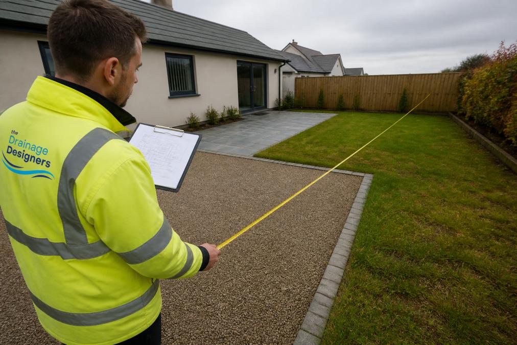
Start by identifying all land from which water flows onto your site. Use an Ordnance Survey map or online mapping tool to trace contours. Water flows downhill perpendicular to contour lines. For our example site, the property boundary is 0.6 hectares. There’s a small area of higher ground to the north (0.1 hectares) that slopes towards the property. Total catchment area = 0.7 hectares.
Step 2: Establish Rainfall Intensity Data
Determine which rainfall event your local authority requires. Most councils ask for a 1-in-1-year event for residential sites. Use the UK Climate Projections rainfall data tables or contact your Local Authority directly for their preferred rainfall intensity values. For our example, the local authority specifies a 1-in-1-year event with intensity 15 mm/hour. If they require a climate change uplift, you’d apply 20%, making it 18 mm/hour.
Step 3: Apply the Runoff Coefficient
Calculate a weighted runoff coefficient based on surface composition. Break down your site by surface type and estimate the proportion of each.
For our example:
- Existing building roof: 0.15 hectares (coefficient 0.9)
- New driveway and patio: 0.12 hectares (coefficient 0.9)
- Existing grass: 0.25 hectares (coefficient 0.4)
- Proposed permeable paving: 0.08 hectares (coefficient 0.5)
Weighted coefficient = [(0.15 × 0.9) + (0.12 × 0.9) + (0.25 × 0.4) + (0.08 × 0.5)] / 0.6 = 0.64
Step 4: Calculate Peak Flow Rate
Apply the Rational Method formula:
Q = C × I × A
Q = 0.64 × 15 × 0.7
Q = 6.72 litres per second
Compare this to greenfield runoff (0.4 × 15 × 0.7 = 4.2 litres per second). Your development increases runoff by 2.5 litres per second, a 60% increase. You’ll need mitigation.
The peak flow rate is the maximum rate at which water leaves your site during a rainfall event. It drives your storage volume requirement and determines whether you need flow rate restriction devices.
Calculating Surface Water Storage Volume for Attenuation
If your developed runoff exceeds greenfield runoff, you’ll need storage to temporarily hold excess water. This is called attenuation storage, and it reduces the peak flow rate by spreading discharge over time.
A simplified approach for small sites uses this formula:
Storage Volume (m³) = 0.5 × (Peak Inflow – Allowable Outflow) × Rainfall Duration (seconds)
For our example:
- Peak inflow: 6.72 litres per second = 0.00672 m³/s
- Allowable outflow: greenfield rate, 4.2 litres per second = 0.0042 m³/s
- Rainfall duration: 30 minutes = 1,800 seconds
Storage Volume = 0.5 × (0.00672 – 0.0042) × 1,800 = 2.27 m³
This storage can take many forms: a detention basin, permeable paving with sub-base storage, a rain garden, or a tank. A detention basin 3 metres × 2 metres × 0.4 metres deep provides 2.4 m³ of storage, sufficient for this example.
Storage volume calculations assume uniform rainfall and simple geometry. Real sites are more complex. Ground infiltration rates, pipe capacities, and site topography all affect actual storage needed. For sites with complex drainage or uncertain ground conditions, [professional hydrological](/611/professional-drainage-design-services-uk/) assessment is strongly recommended.
SuDS Drainage Strategy Requirements and Regulatory Compliance
Sustainable Drainage Systems (SuDS) are now a regulatory requirement for most new developments in the UK. The requirement comes from Part H of the Building Regulations and from planning policy, which typically demands that surface water drainage incorporates SuDS principles unless demonstrated to be unfeasible.
SuDS include permeable pavements, green roofs, swales, rain gardens, detention basins, and infiltration trenches. The hierarchy prioritises infiltration first (water soaks into ground), then attenuation and reuse, then controlled discharge to watercourses or sewers.
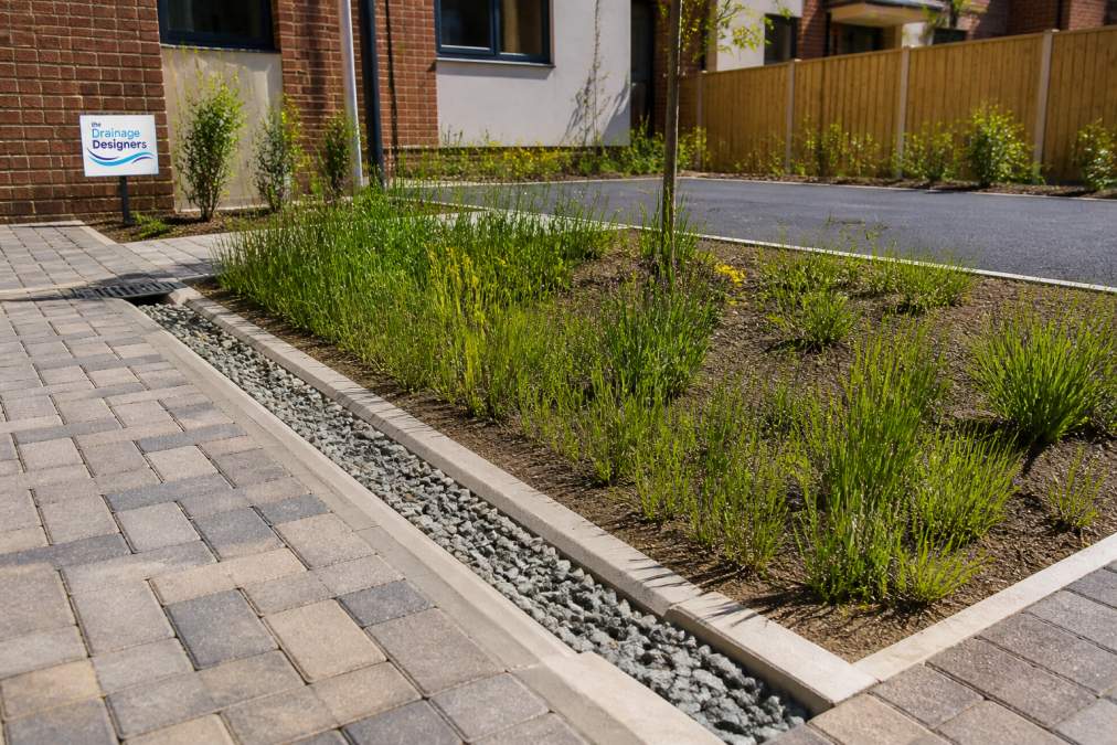
Your local authority will have a SuDS design guide or drainage strategy that specifies which techniques are acceptable. Key compliance steps are:
1. Demonstrate SuDS feasibility. Show that infiltration, attenuation, or reuse is technically possible on your site. If ground conditions prevent infiltration (clay soils, high water table), document this and explain your alternative approach.
2. Prioritise the SuDS hierarchy. If infiltration is feasible, use it. If not, propose attenuation. If neither works, propose controlled discharge with flow rate restriction.
3. Design for the required rainfall event. Most councils ask for 1-in-1-year events for residential, 1-in-5-year for commercial. Some now require 1-in-100-year events with a climate change uplift.
4. Provide maintenance access. SuDS features need inspection and cleaning. Ensure your design allows vehicle or pedestrian access to detention basins, swales, and permeable surfaces.
5. Submit a drainage strategy with calculations. This must show: catchment area, rainfall intensity, runoff coefficients, peak flow rates, greenfield comparison, storage volume, and proposed SuDS features.
The Environment Agency’s guidance on sustainable drainage provides detailed technical standards. Your local Lead Local Flood Authority (LLFA) also publishes local design standards, which are legally binding for your area.
Common Mistakes to Avoid When Calculating Runoff
Most errors in runoff calculations fall into predictable categories.
Underestimating catchment area. Designers often ignore uphill ground that contributes runoff. A site surrounded by higher terrain can have a catchment area 50% larger than the property boundary. Always trace contours carefully and include all contributing land.
Using the wrong rainfall intensity. Confusing 1-in-1-year with 1-in-100-year events is common. Check your local authority’s requirements explicitly. Using too low an intensity understates your runoff and leads to undersized drainage systems.
Applying an incorrect runoff coefficient. Using 0.9 for all paved surfaces is reasonable, but forgetting to include roofing (also 0.9) or overestimating the permeability of permeable paving throws the calculation off. Build a detailed surface breakdown and justify each coefficient with reference to design guidance.
Ignoring infiltration potential. Some sites have excellent infiltration through sandy or gravelly soils. If you assume all runoff must be stored or discharged, you miss opportunities to reduce storage volume. A site investigation or soil percolation test can reveal whether infiltration is viable.
Forgetting the climate change uplift. Many authorities now require a 20% increase to rainfall intensity. If you omit this, your storage is undersized. Check your authority’s latest guidance.
Mixing units carelessly. Catchment area in hectares, rainfall in millimetres per hour, and flow in litres per second are standard in the UK. Accidentally using square metres instead of hectares multiplies your error by factors of 100 or more. Double-check units at every step.
Not comparing to greenfield runoff. If you don’t calculate greenfield runoff as a baseline, you won’t know whether your development increases flood risk. This is the key question councils ask.
When to Seek Professional Assessment
For straightforward sites and small residential extensions with simple drainage, a competent designer can often handle the calculation using the method described above. However, several scenarios warrant professional input.
Complex topography or large catchment areas. If your site has significant uphill contribution, multiple drainage paths, or a catchment area over 2 hectares, professional hydrological modelling provides more accuracy than the Rational Method.
Uncertain ground conditions. If you don’t know your soil type, infiltration rate, or groundwater depth, a site investigation is essential. Designing SuDS without this information risks failure or regulatory non-compliance.
Flood risk or environmental sensitivity. Sites in flood zones, near watercourses, or in areas of environmental designation often need specialist flood risk assessment. This goes beyond runoff calculation and requires expertise in fluvial modelling and environmental impact.
Planning history or council concerns. If your site has had previous drainage-related planning refusals, or if your local authority is known for rigorous drainage scrutiny, professional design adds credibility and reduces rejection risk.
SuDS integration and landscaping. If you want to combine drainage with landscape design, rain gardens, green roofs, and permeable paving that serves multiple functions, a specialist can optimise both performance and aesthetics.
The Drainage Designers work with architects, developers, and homeowners across the UK to handle exactly these scenarios. From site investigation and runoff calculation through to planning submission and construction supervision, we simplify the process and ensure your drainage design meets local authority requirements first time.
Calculating surface water runoff for small sites requires careful measurement of three variables: catchment area, rainfall intensity, and runoff coefficient, then applying the Rational Method formula. The process is methodical and transparent, which is why councils expect to see it in planning submissions. Most small residential extensions can be handled using publicly available rainfall data and straightforward calculations. However, sites with complex topography, uncertain ground conditions, or previous planning challenges benefit from professional assessment. The Drainage Designers provide expert drainage design solutions tailored for small sites, managing site investigations, runoff calculations, SuDS integration, and local authority liaison to ensure your project secures planning approval and delivers a compliant drainage system on schedule.
Frequently Asked Questions
What is the equation for calculating surface water runoff?
The rational method uses the formula: Q = CiA, where Q is peak flow rate (litres per second), C is the runoff coefficient (0 to 1), i is rainfall intensity (millimetres per hour), and A is the catchment area (hectares). This straightforward calculation estimates the volume of water that will run off impermeable surfaces during a design storm event. For small sites, this method provides a practical, defensible approach that most Local Authorities accept in planning submissions.
How do I calculate the greenfield runoff rate for my site?
Greenfield runoff rate estimation requires determining the rate at which water would drain from an undeveloped site in its natural state. You need the pre-development soil infiltration rate, rainfall intensity for your region, and the site area. The Environment Agency provides regional hydrometric data to support this calculation. Your Local Authority and Lead Local Flood Authority may specify which data source to use.
What rainfall intensity should I use for my calculations?
Use rainfall intensity data from the Flood Estimation Handbook (FEH) or equivalent hydrological assessment tools relevant to your region. Most small site drainage calculations use a 1 in 1-year rainfall event for routine design, though your Local Authority may require a 1 in 100-year event for flood risk assessment. The rainfall intensity varies by location and return period; check with your Lead Local Flood Authority for site-specific recommendations. Climate change allowances may require using higher intensity figures than historical data suggests.
Do I need a drainage strategy for a small residential extension?
Yes, most residential extensions that create or increase impermeable surface require a drainage strategy to meet planning conditions. If your extension adds paved areas, roof space, or other surfaces that prevent water infiltration, you must demonstrate how surface water will be managed and where it will drain. The strategy must show either connection to existing drainage, infiltration into permeable ground, or storage and attenuation. Many councils reject planning applications that lack a compliant drainage strategy, so addressing this early prevents costly delays.
This article was written using GrandRanker